 |
 |
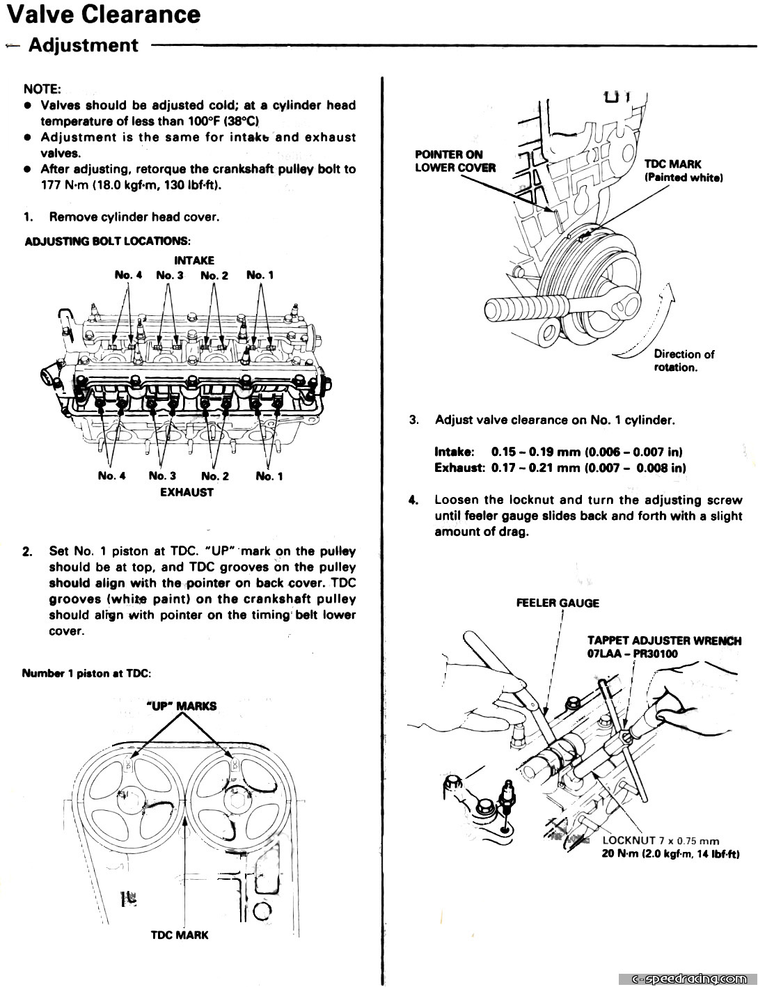
Before starting, take a look a the instructions from the Helms manual. If you don't have one, then you're in luck. Just click the images on the left and print them out. |
 |
 |
Step 1:
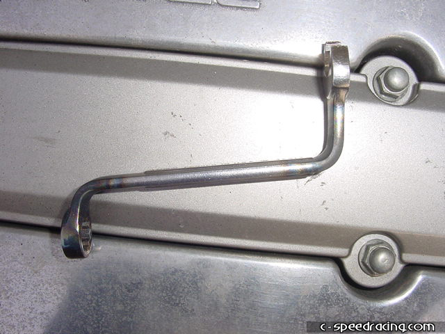
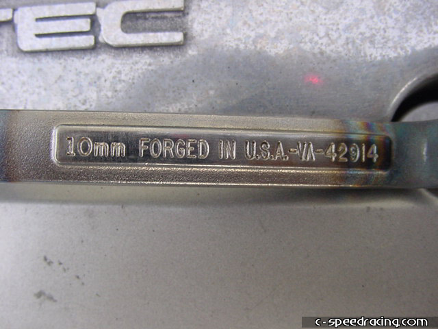
Before starting, the engine must be cool (below 100F or 38C). Also be sure you have all the required tools. The most important is the lock nut wrench. We opted to modify a 10mm Craftsman box wrench which works extremely well, however voiding its lifetime warrenty (of course). Snap-on also carries a Honda specific valve adjustment tool with the socket and slot head screwdriver built into one for around $40USD. |
 |
 |
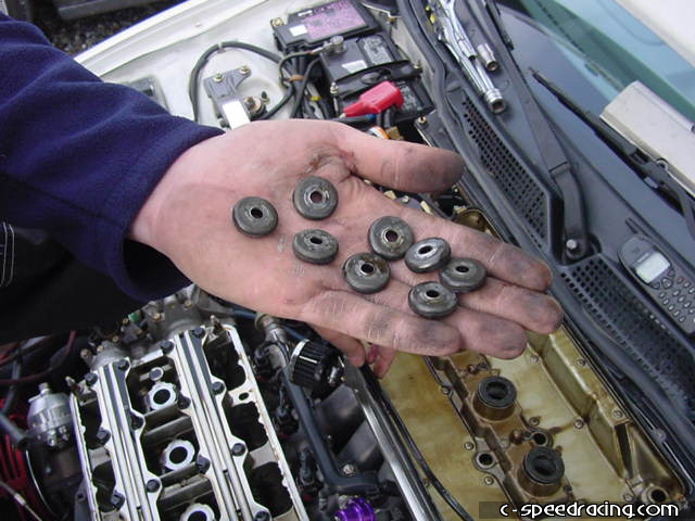
Step 2:
Remove the valve cover by removing the 8 x 10mm nuts around the perimeter of the valve cover and on the spark plug wire cover. Then don't forget to remove the 4 x 10mm nuts that are also under the spark plug wire cover when you pull off the plug wires. You will also need to remove the 10mm bolts holding down the ground strap on the front of the valve cover and the other one on the rear holding the power steering line bracket. Don't lose the washers either! |
 |
 |
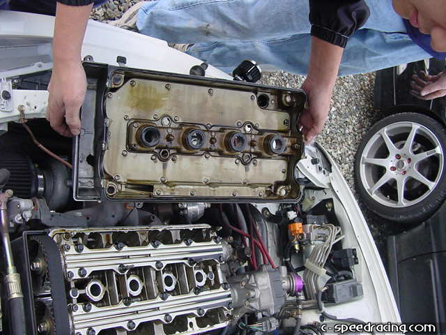
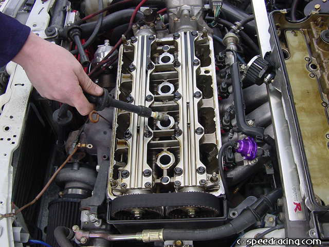
Step 3:
Now pull off the valve cover being careful not to tear the valve cover gasket as you can most likely reuse it. |
 |
 |
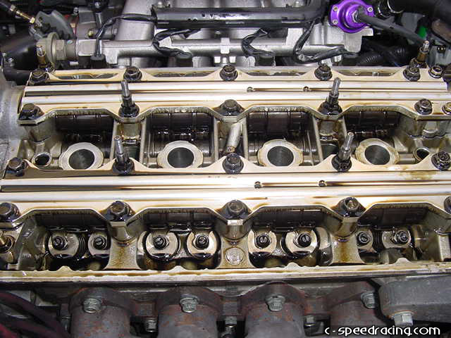
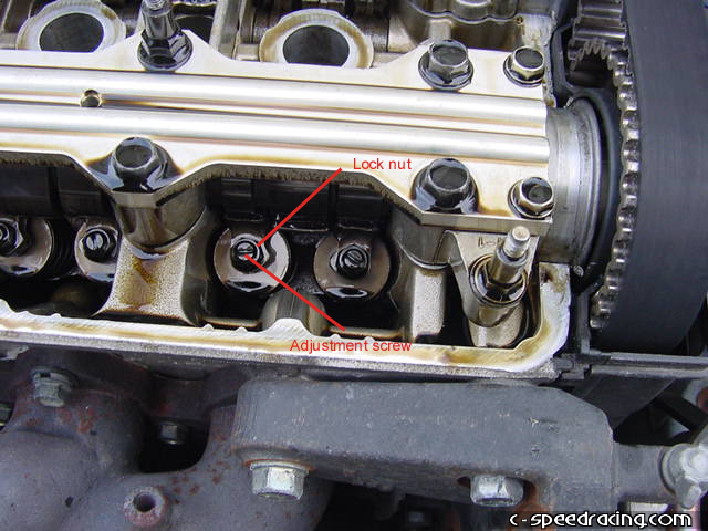
Step 4:
You can now see the adjustment screw and the lock nut on each valve. It will also make it easier to turn the motor over if you remove the spark plugs. But it isn't necessary. We remove them because we are weak. |
 |
 |
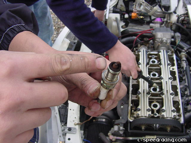
Step 5:
If you remove the plugs, be sure to inspect them as they can tell you a lot about how the car is running. A light brown color indicates a perfect A/F mixture. White is lean likewise black indicates rich. If you see dampness or oil on it, then you are in trouble. TIP: Sometimes its easier to pull the plugs out of the block by using the plug wires to grab them after you've loosened them if you don't have a spark plug socket. |
 |
 |
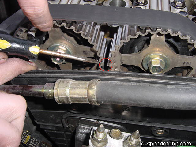
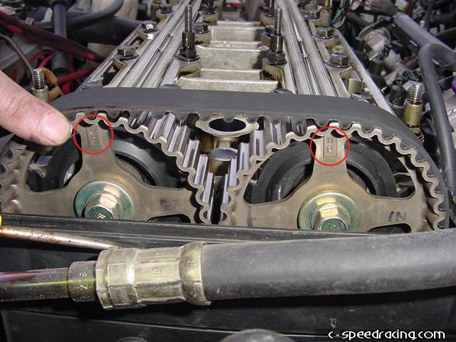
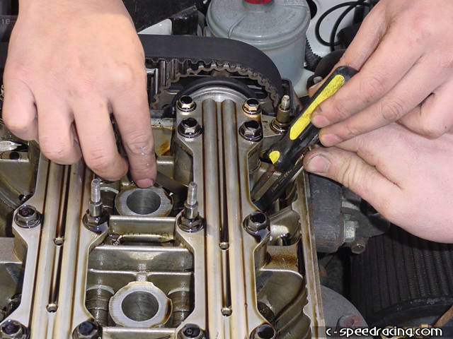
Step 6:
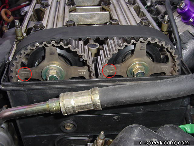
Here's the most important step before starting the actual valve adjustment. You have to be sure to crank the motor over to TDC for each cylinder that you are adjusting. We will be starting on the #1 cylinder, so you must use the 19mm socket on the crank pulley and manually turn the motor over until the UP marks on the cam gears are pointing straight up and the indicator marks on the cam teeth are side by side. |
 |
 |
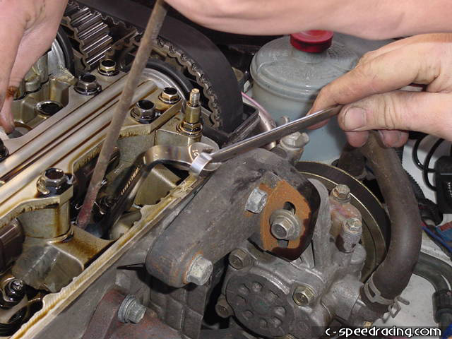
Step 7:
Once everything is lined up for the first cylinder, you can go ahead and loosen the lock nut on each intake and exhaust valve using the 10mm wrench or specialty tool. |
 |
 |
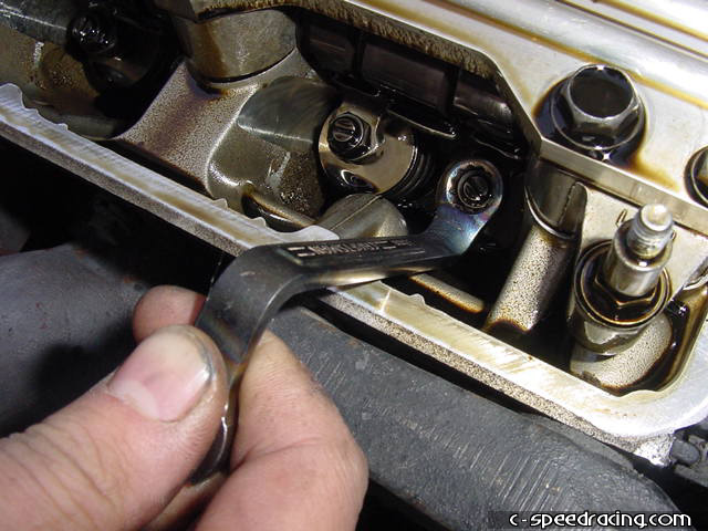
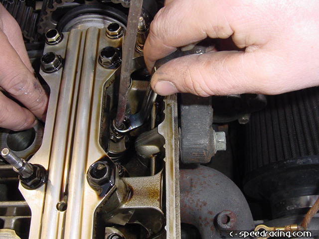
Step 8:
Start with the exhaust valves. Using the 0.007" angled feeler gauge, insert it between the cam lobe and lifter. Place the slot head screwdriver on the adjustment screw along with the 10mm wrench on the lock nut all at the same time. |
 |
 |
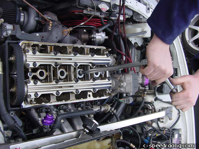
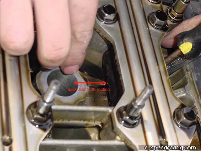
Step 9:
While using a back and forth motion with the feeler guage (it takes practice), turn the adjustment screw (right = tight, left = loose) until you feel a slight drag on the feeler guage. Make sure you have the feeler gauge straight as if it is slightly at an angle it will feel as if it were adjusted right but in reality will end up being a little loose. Once you feel that you have it in the right place, hold the screwdriver firmly and tighten the lock nut down until it is snug. Do not over tighten. If you do not hold the screwdriver fimly, the adjustment screw may tighten as you turn the lock nut so be careful. If you need more leverage on the modified wrench, you can link another wrench to the end of it as shown in the previos step. |
 |
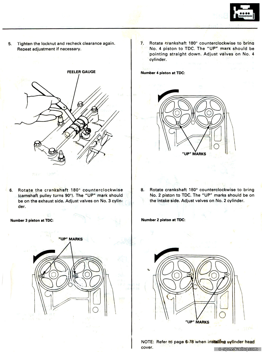
Step 10:
Once you're done with the exhaust, do the same thing for the intake side. Be sure to use the 0.006" angled feeler gauge! Then repeat the steps for the next 3 cylinders by rotating the crank counter-clockwise 180deg at a time. Adjust them according to the firing order: 1-3-4-2.
Once your done, double check that all the lock nuts are tight and then replace the valve cover gasket and valve cover. Replace the plug wires in their proper position and you should be ready to start the car. |