 |
 |
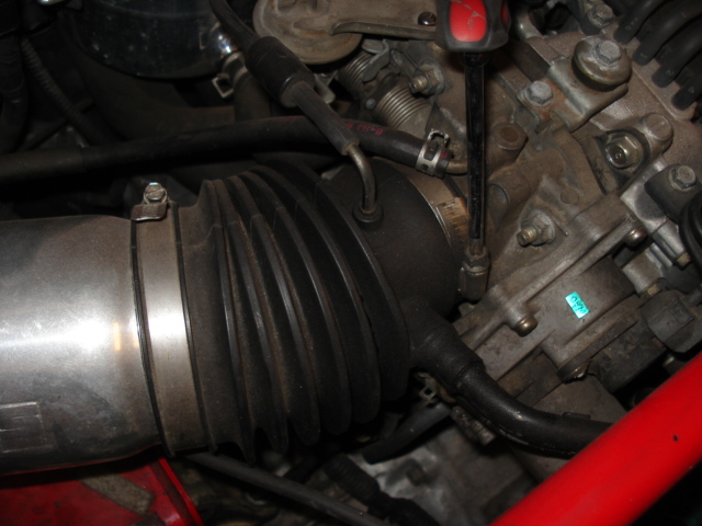
The first step is to jack up the rear of the car as high as possible and place it on jack stands. Drain the gearbox fluid. Then working from the engine first, remove the intake tube. Then disconnect all the plugs from the control box. |
 |
 |
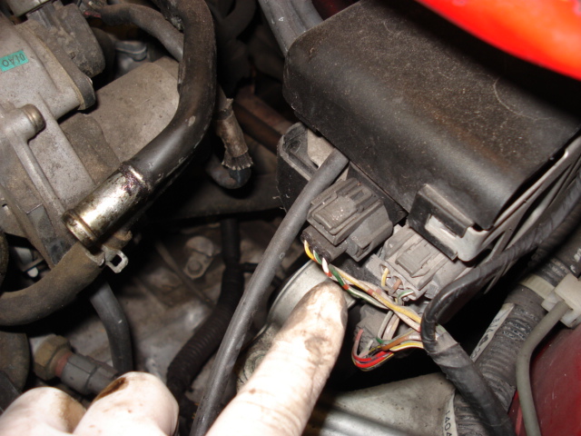
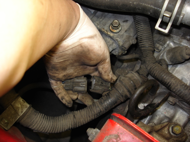
Then remove the two 10mm bolts securing the control box to the chassis and set the control box on the intake manifold cover. Make sure you do not accidentally disconnect the vacuum lines by the throttle body. |
 |
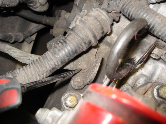 |
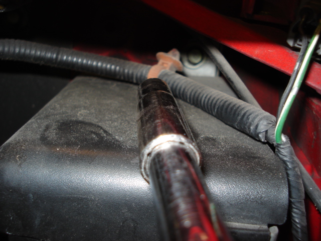
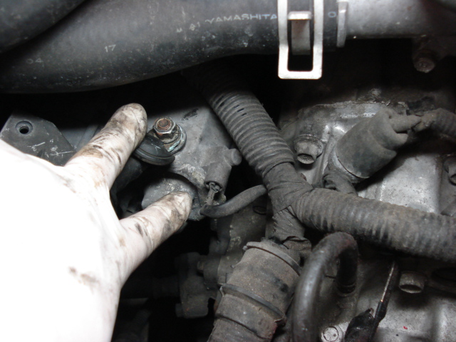
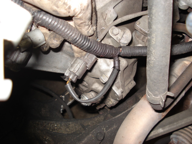
Now disconnect the reverse light sensor plug and remove the 10mm bolt securing the ground strap. |
 |
 |
Next, disconnect the power and signal wire to the starter. Then remove the two 14mm bolts securing the starter to the gearbox. At this point, also remove the four upper 17mm gearbox bolts on the driver side. |
 |
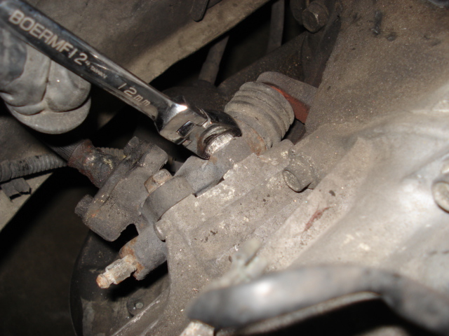 |
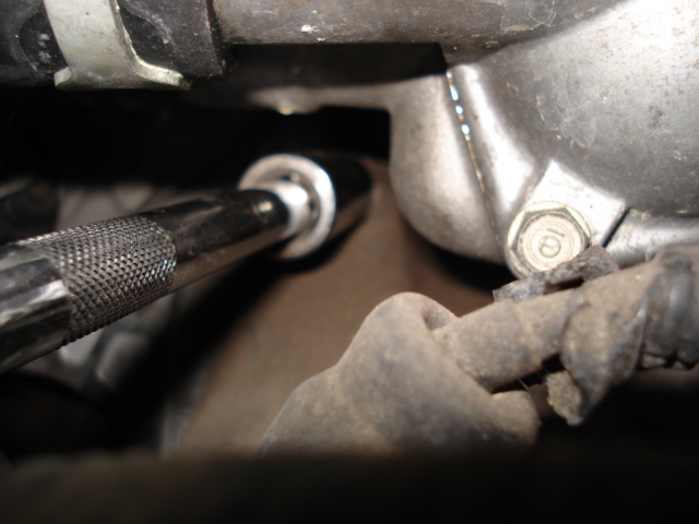
Disconnect the vehicle speed sensor plug. Remove the two 12mm bolts securing the clutch slave cylinder to the gear box. Set the clutch slave cylinder to the side of the engine bay. |
 |
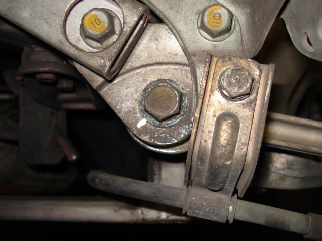 |
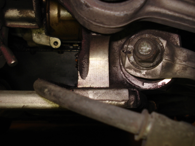
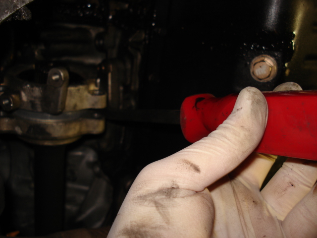
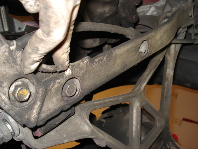
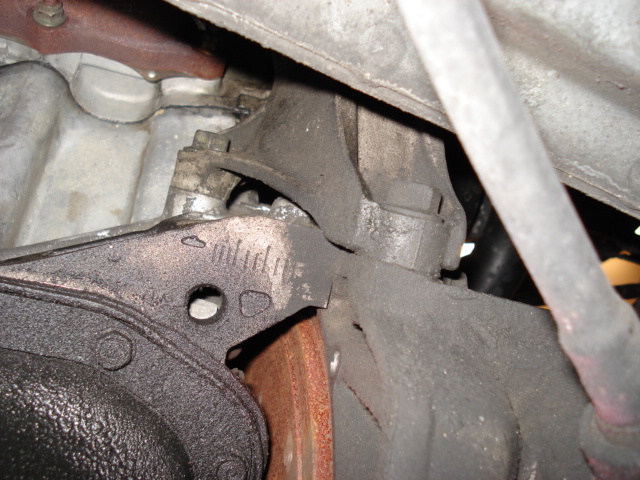
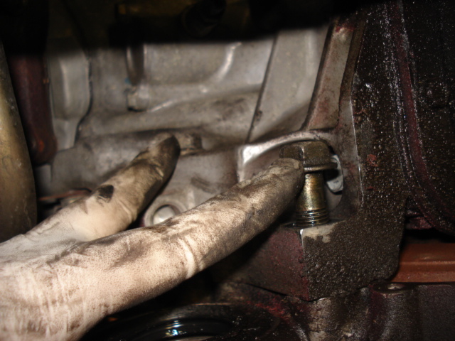
Now, remove the rear sway bar end link bolt from the hub and damper. Pull the end link bolt out of the hub and swing it out of the way. Then remove the 12mm bolt holding the e-brake cable bracket. Also remove the 19mm bolt securing the rear toe arm. These are the two lower bolts pictured on the left. |
 |
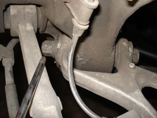 |
Disconnect the lower control arm from the subframe by first removing the rear 19mm bolt. Be sure to mark the camber adjustment on the rear bolt with a marker. |
 |
 |
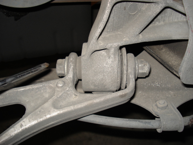
Then remove the front 19mm bolt from the lower control arm. Also unbolt the the ABS sensor wire bracket. Disconnect the lower control arm and damper on the other side as well. Now the rear hubs should dangle freely from the upper control only. |
 |
 |
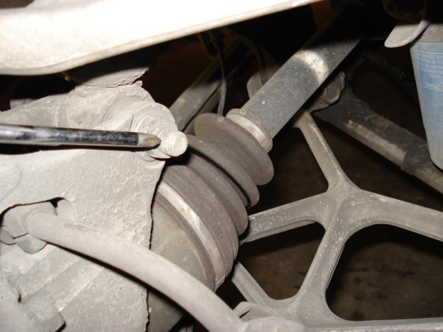
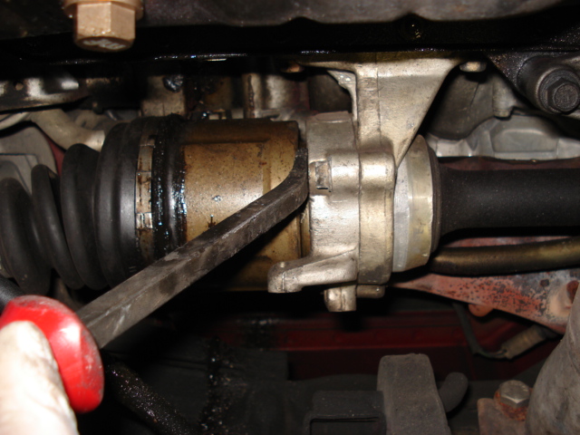
Now, use a pry bar to seperate the passenger side axle from the intermediate shaft. Once you've pried it out about 1/4" you can grab the hub and axle assembly together and pull it away from the intermediate shaft. On the driver side, simply use a pry bar and pry against the gearbox housing to pop the axle out of the gearbox. |
 |
 |
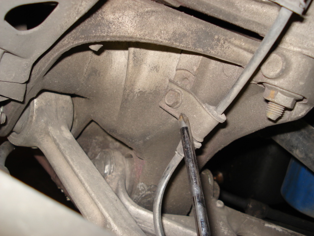
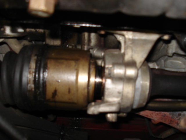
With the passenger side axle out of the way, you can now remove the three 12mm bolts securing the intermediate shaft to its' bracket. Then using a small flat head screw driver, seperate the intermediate shaft from its' bracket. |
 |
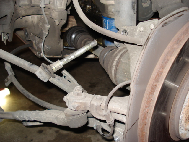 |
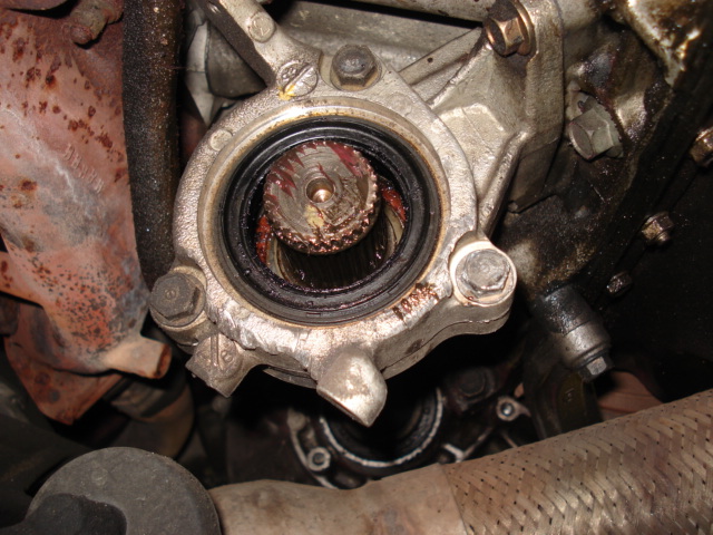
Once there is enough room between the intermediate shaft and the bracket, using a pry bar to fully seperate it and remove the intermediate shaft from the gearbox. You can see in the picture on the left that the axle has been disconnected from the intermediate shaft and left dangling, along with the sway bar end link, rear toe bar and ABS sensor wire. |
 |
 |
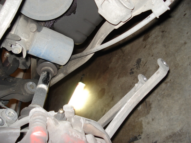
Pictured on the left shows the axle, rear lower control arm, end link, e-brake cable bracket and ABS sensor wire disconnected. |
 |
 |
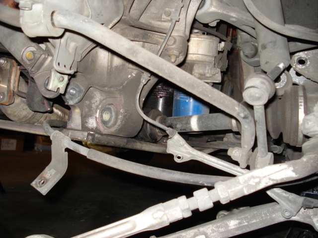
Now, remove the rear lower subframe brace. There are several 14mm nuts and bolts securing it to the subframe. Also remove the brackets securing the e-brake cables to the brace. |
 |
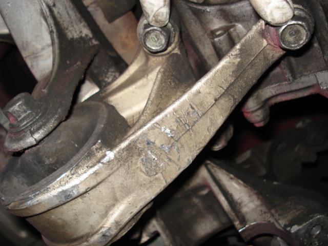 |
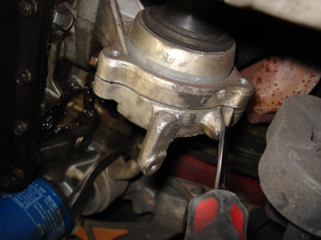
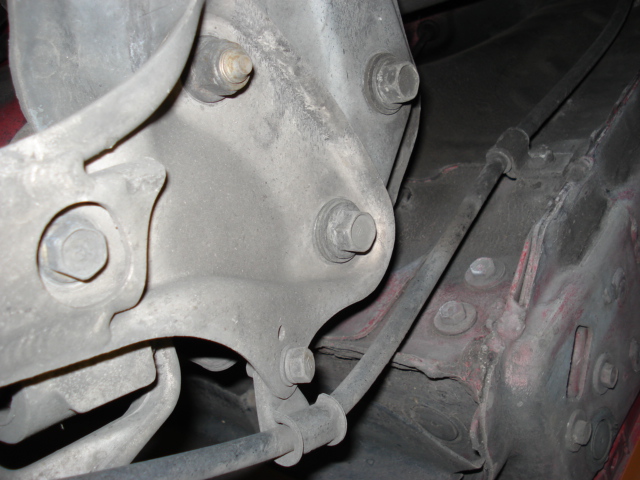
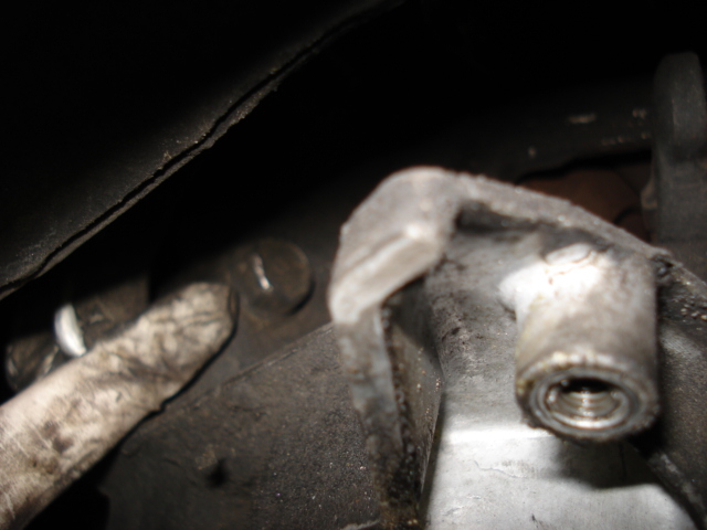
Remove the lower gearbox brace bolt and then remove the rear engine mount. There are three bolts securing the moun to the engine/gearbox and one long nut/bolt to the subframe. |
 |
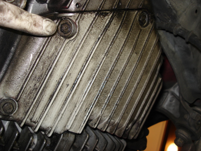 |
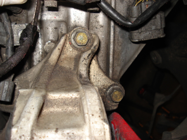
You can now remove the three bolts securing the front engine mount to the engine. A rachetting 14mm wrench comes in real handy here as the space is tight. You do not need to remove the mount from the cross member. Then remove the lower shift cable cover by removing the 10mm bolts. |
 |
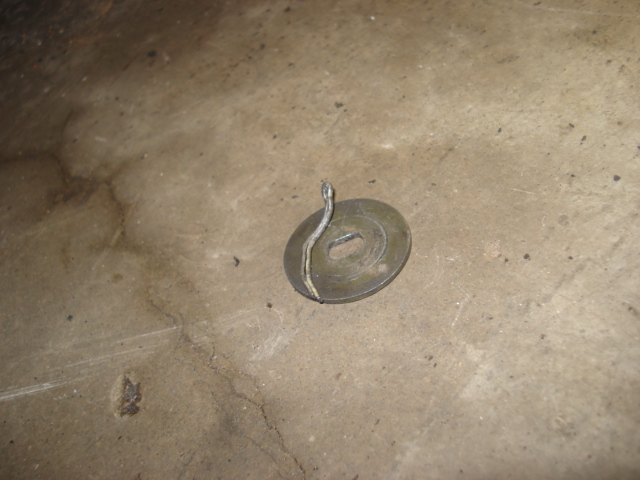 |
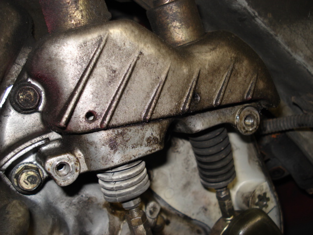
Now's the tricky part. The two shift cables are secured to the gearbox with a cotter pin. You cannot see the cotter pins however as they are on the top side. They are soft enough to bend by hand, so by feel, bend them straight and using a 90 degree pick, pull them out. Then remove the shifter cable mount by removing the remaining 10mm bolts. |
 |
 |
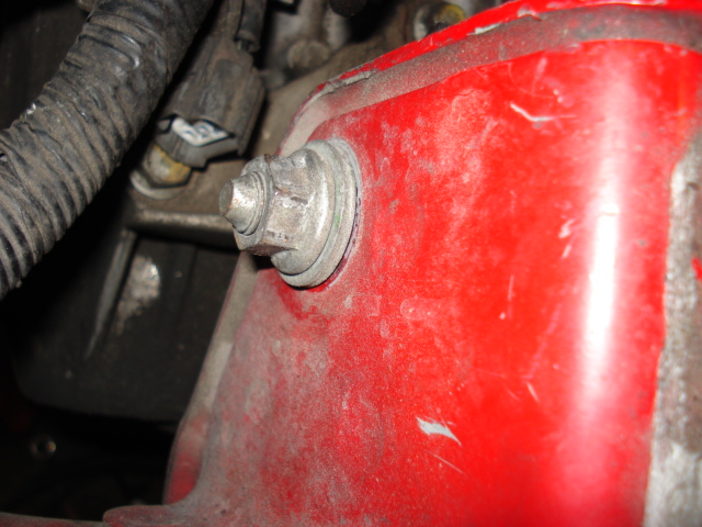
Now, remove two 17mm gearbox bolts on the passenger side from under the car. There is also one more on the driver side above where the front engine mount was. |
 |
 |
Place a jack stand and a block of wood under the engine to hold it up so it doesn't sag. Tilting the engine slightly downwards on the driver side can aid removing/installing the gearbox. Then remove the three 14mm bolts securing the driver side upper mount to the gearbox. Also remove the 17mm bolt from the chassis, then remove the mount completely. The gearbox is now free to come out. Before seperating the gearbox from the engine, you MUST pull the clutch fork outwards so it is no longer engaged on the release bearing! Carefully, seperate the gearbox from the engine - with a pry bar if needed - and set it on the ground. It helps if you use a jack to help lower the gearbox as it is quite heavy. |
 |
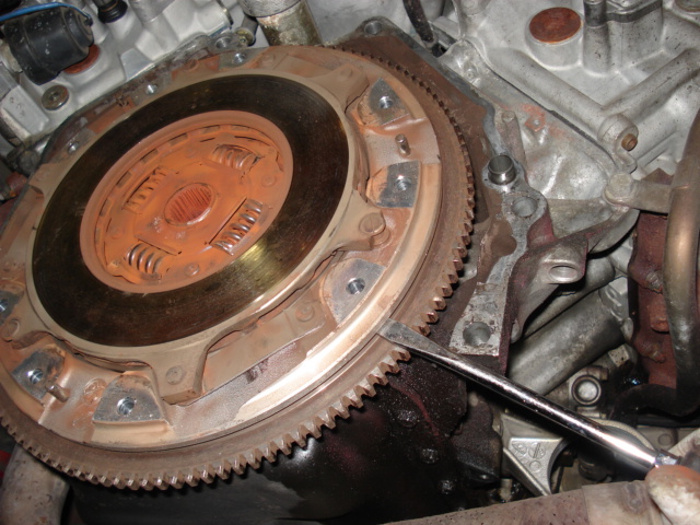 |
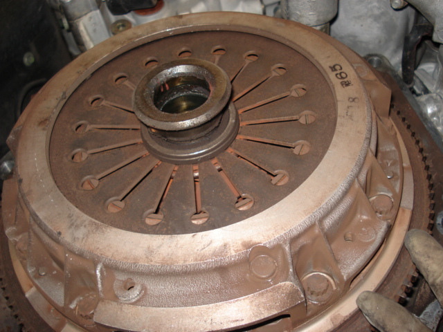
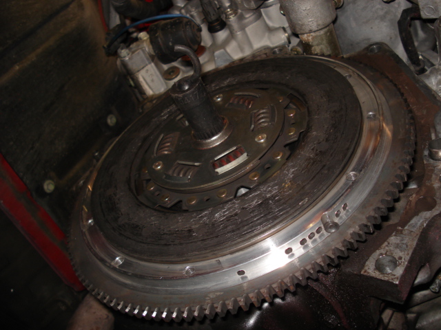
With the gearbox out of the way, you can now remove the clutch and pressure plate. There are six 12pt 10mm bolts securing the pressure plate to the flywheel. Once the pressure plate is removed, you'll need to pry the mid plate off the flywheel to remove the rear clutch disc and expose the flywheel bolts. |
 |
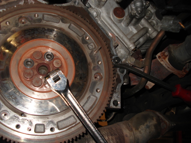 |
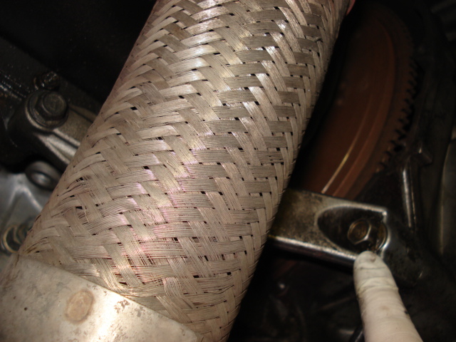
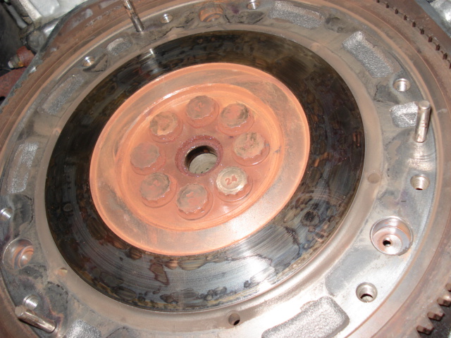
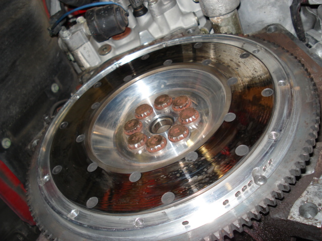
Remove the flywheel bolts. If you do not have an impact gun powerful enough to remove the bolts, then you can secure the flywheel from spinning but using a 17mm bolt (or the dowel pin) and pry bar as pictured on the left. Insert the pry bar into the flywheel teeth to keep it from spinning. This is a two person task. |
 |
 |
Now you can install the new flywheel. Be sure the clean the surface with brake cleaner as any oily residue will reduce clutch performance. Make sure you use a clutch alignment tool. Without one, you will have a lot of difficulty reinstalling the gearbox to the engine - you've been warned! Also make sure the clutch disc(s) face the correct direction. In this case, on a single disc clutch, the 'thicker' center side (where the springs are) faces towards the pressure plate. |
|
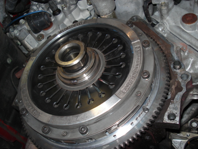 |
Install the pressure plate to the flywheel. Be sure to install the release bearing first! Be sure the torque the pressure plate. Reinstall the gearbox - again, it helps if you set it on the jack and raise it up to the engine. Make sure the clutch fork is in place but not secured to the gearbox. You must have the gearbox mated to the engine first, then push the clutch fork onto the release bearing. Complete the job using the reverse process. |